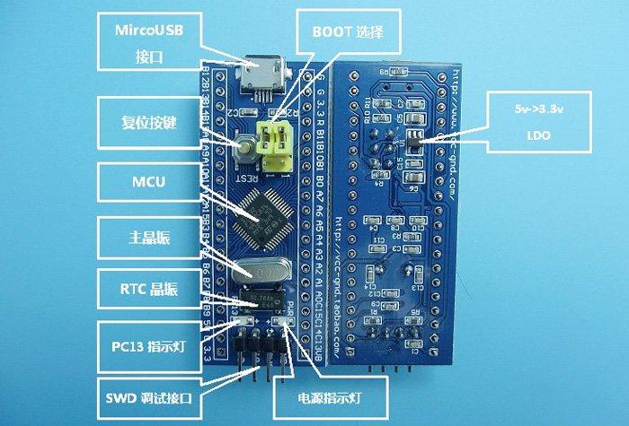
Being a sucker for a bargain and wanting to get into basic ARM development I’ve bought a couple of STM32 boards in the past, these tend to be low cost and one of the variants is below. Basically this is just the STM32 chip with breakout connectors attached. For ease of use I noticed that you can use the Arduino IDE to develop and upload simple test projects, probably not what the purists would like to see but for me a gentle introduction
The trouble with these low cost breakout boards is that the documentation is non existent but luckily some kind hearted people have been through the pain, here are some useful links. Here is the first one, it is commonly called – STM32 Minimum System Development Board for Arduino. Why Arduino, who knows other than trying to cash in on the popularity, it is possible as we will try and explain to add support to the Arduino IDE but this is never documented with the boards.

I recommend you following the instructions at – http://www.rogerclark.net/stm32f103-and-maple-maple-mini-with-arduino-1-5-x-ide/
Newer Arduino IDE versions will need to do the following – http://www.rogerclark.net/work-around-for-arduino-stm32-with-ide-v-1-6-3-or-newer/ , basically you need to go to the Board Manager and install support for the ARduino Due.
Connection –
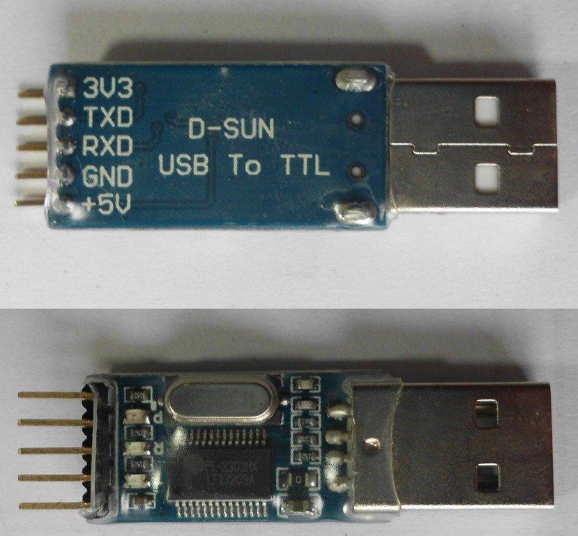
I connected a Prolific PL2303 USB-to-Serial port adapter to my STM32 like this. AN FTDI or Cp2102 are other common options, as long as there is a usable COM port it shouldn’t make a difference

3.3v – Any 3.3v on the board – usually marked 3.3
TX – A10
RX – A9
Gnd – Any Gnd on the board , I used the SWD one. Usually marked up as G on the board
Now at first I recieved an error message – Got NACK from device on command 0x43. Looking at the post at http://www.stm32duino.com/viewtopic.php?f=20&t=747&sid=cd8271c9e0bb7f11cb9c230520a67697&start=10 , I followed the steps below as mentioned in one of the posts
It sounds like the chip has been locked, and will need to be fully erased and unlocked before you can do anything
Try downloading STM’s “Flash loader demonstrator” (its not really a demonstrator its the flash uploader via serial)
http://www.st.com/web/en/catalog/tools/PF257525
This removed the issue for me, this is the code you will need for a simple example, the board mentioned earlier has an LED connected to PC13 we will flash this on and off
Code
[codesyntax lang=”cpp”]
// the setup function runs once when you press reset or power the board
void setup() {
// initialize digital pin PC13 as an output.
pinMode(PC13, OUTPUT);
}

// the loop function runs over and over again forever
void loop() {
digitalWrite(PC13, HIGH); // turn the LED on (HIGH is the voltage level)
delay(1000); // wait for a second
digitalWrite(PC13, LOW); // turn the LED off by making the voltage LOW
delay(1000); // wait for a second
}
[/codesyntax]
Click on the reset button of the board and upload the sketch via the IDE, in the preferences of the IDE I check Verbose warning. Here is what i saw on a good upload, you should see something similar
[codesyntax lang=”dos”]
http://stm32flash.googlecode.com/

Using Parser : Raw BINARY
Interface serial_w32: 230400 8E1
Version : 0x22
Option 1 : 0x00
Option 2 : 0x00
Device ID : 0x0410 (Medium-density)
- RAM : 20KiB (512b reserved by bootloader)
- Flash : 128KiB (sector size: 4x1024)
- Option RAM : 16b
- System RAM : 2KiB
Write to memory
Erasing memory

Wrote address 0x08000100 (3.91%)
Wrote address 0x08000200 (7.82%)
Wrote address 0x08000300 (11.73%)
Wrote address 0x08000400 (15.64%)
Wrote address 0x08000500 (19.55%)
Wrote address 0x08000600 (23.46%)
Wrote address 0x08000700 (27.37%)
Wrote address 0x08000800 (31.28%)
Wrote address 0x08000900 (35.19%)
Wrote address 0x08000a00 (39.10%)
Wrote address 0x08000b00 (43.01%)
Wrote address 0x08000c00 (46.92%)
Wrote address 0x08000d00 (50.82%)
Wrote address 0x08000e00 (54.73%)
Wrote address 0x08000f00 (58.64%)
Wrote address 0x08001000 (62.55%)
Wrote address 0x08001100 (66.46%)
Wrote address 0x08001200 (70.37%)
Wrote address 0x08001300 (74.28%)
Wrote address 0x08001400 (78.19%)
Wrote address 0x08001500 (82.10%)
Wrote address 0x08001600 (86.01%)
Wrote address 0x08001700 (89.92%)
Wrote address 0x08001800 (93.83%)
Wrote address 0x08001900 (97.74%)
Wrote address 0x08001994 (100.00%) Done.

Starting execution at address 0x08000000... done.
[/codesyntax]
Overall its a nice low cost board, like a lot of these Chinese type electronic development boards and kits if you can get over the initial challenge of actually getting the board to do anything then its quite useful, its been a while since I got so excites at a simple LED flashing example.
Links
 1pcs STM32F103C8T6 ARM STM32 Minimum System Development Board Module For arduino

