
2.6K
In this example we will create a simple flashing led example for the MINI STM32 board, I used this to test out a J-link from segger and also to try out the MikroC Pro for ARM IDE.
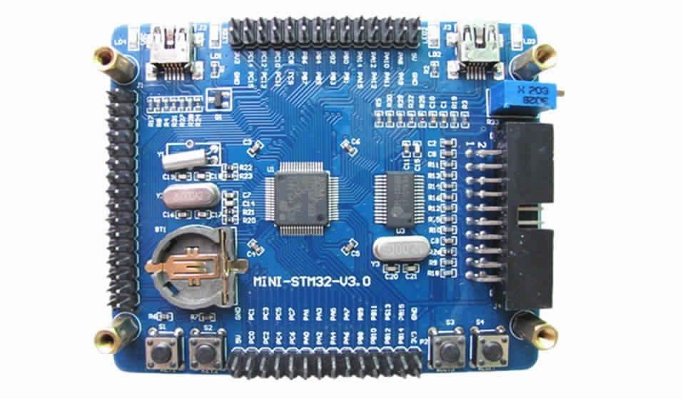
Here is a picture of the board, it is commonly found on many internet sites
mini stm32
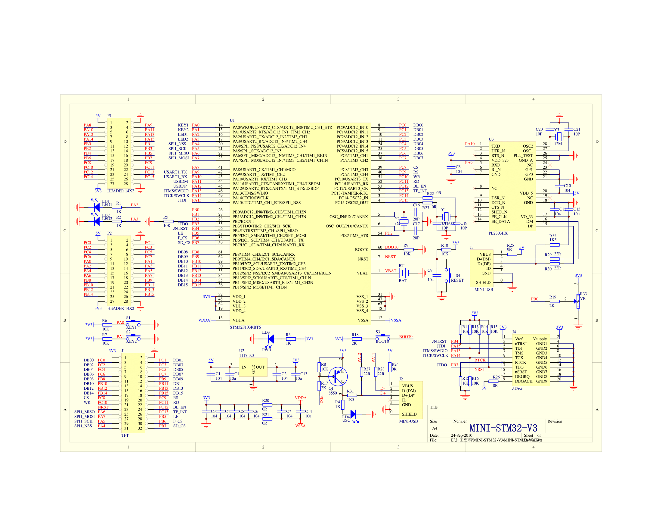
Here is a schematic for the board, you can see 2 LEDs fitted to PA1 and PA2 these will flash on and off
MINI_STM32-V3.0 schematic
Code
The code example was written in MikroC PRO for ARM, I used a J-link to program the MINI STM32 via the jtag connector. It will actually toggle all the I/O pins low and high
[codesyntax lang=”cpp”]
void main() {
  GPIO_Digital_Output(&GPIOA_BASE, _GPIO_PINMASK_ALL); // Set PORTA as digital output
  GPIO_Digital_Output(&GPIOB_BASE, _GPIO_PINMASK_ALL); // Set PORTB as digital output
  GPIO_Digital_Output(&GPIOC_BASE, _GPIO_PINMASK_ALL); // Set PORTC as digital output
  GPIO_Digital_Output(&GPIOD_BASE, _GPIO_PINMASK_ALL); // Set PORTD as digital output
  GPIO_Digital_Output(&GPIOE_BASE, _GPIO_PINMASK_ALL); // Set PORTE as digital output

  GPIOA_ODR = 0;
  GPIOB_ODR = 0;
  GPIOC_ODR = 0;
  GPIOD_ODR = 0;
  GPIOE_ODR = 0;

  while(1)
  {
    GPIOA_ODR = 0xff;
    GPIOB_ODR = 0xff;
    GPIOC_ODR = 0xff;
    GPIOD_ODR = 0xff;
    GPIOE_ODR = 0xff;
    Delay_ms(1000);
    GPIOA_ODR = 0;
    GPIOB_ODR = 0;
    GPIOC_ODR = 0;
    GPIOD_ODR = 0;
    GPIOE_ODR = 0;
    Delay_ms(1000);
  }
}
[/codesyntax]
Links
MINI stm32 Core Board Supporting screen 320×240 with Touch Screen
